


Analog Discovery Pro 2450 Mixed Signal Oscilloscope
Analog Discovery Pro 2450 Mixed Signal Oscilloscope
High-Speed, High-Bandwidth Mixed Signal Oscilloscopes
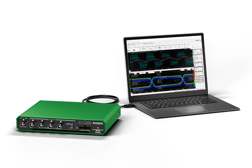
The Analog Discovery Pro 2440 and Analog Discovery Pro 2450 deliver serious measurements for the engineer who knows what matters. Choose between four analog channels of either 100 MHz bandwidth at 12-bit resolution (ADP2440) or 200 MHz bandwidth at 8-bit resolution (ADP2450) with both featuring a 16 channel Logic Analyzer and Pattern Generator, an arbitrary waveform generator, and seamless integration with the WaveForms software.
These USB 3.2 oscilloscopes provide the right level of performance where you need it. Circuit design, embedded systems, or your own unique test workflow; you can do it all without distracting from your task at hand. When you need a real tool to solve real problems, use the Analog Discovery Pro.
Analog Inputs
- Four BNC input channels with 8-bit resolution with up to ±25 V input range
- 200+ MHz bandwidth, 1 GS/s interleaved
- 10 different hardware input ranges from ±25 mV to ±25 V for multiple levels of precision
- User selectable 50 Ω or 1 MΩ input impedance
- Many additional views including FFT, Histogram, Persistence, Eye Diagram, and Analog-to-Digital plots
- Complex trigger support including Edge, Pulse, Timeout, Glitch, Transition, and Window conditions
- Dedicated Spectrum Analyzer, Network/Bode Plot Analyzer, and Impedance Analyzer instruments
Analog Output
- One BNC output function generator channel with 14-bit resolution, ±5 V output range
- 15+ MHz bandwidth, up to 125 MS/s
- Standard, Advanced, and Custom Waveforms supported
- Sine, Square, Triangle, Ramp, DC, Pulse, Noise, Burst
- Uni and Bidirectional Frequency and/or Amplitude Sweep
- Multiple modulation techniques including AM, FM, PM, and Summation
Digital I/O
- 16 digital I/O for the Logic Analyzer and Pattern Generator with fully configurable tri-state buffers
- Internally clocked up to a 1.2 GS/s sampling rate
- Many protocol analyzers including SPI, I2C, UART, 1-Wire, CAN, GPIB, I2S, LIN, JTAG, Manchester, SAE JA1850, and Quadrature Decoders
- Protocol generation support for SPI, UART, I2C, CAN, HDMI CEC, SWD, and AVR
- Two bidirectional BNC triggers for external and internal triggering
Additional Features
- Dual Mode to operate two devices simultaneously for 8 analog inputs, 32 digital I/Os, and 2 AWGs
- Automatic device phase adjustment between devices in Dual Mode
- USB 3.2 (5 Gbps) transfer speeds
- Triggering system allows Scope, AWG, and Digital I/O subsystems to trigger off of each other or external trigger inputs and forward triggers to other instruments
- Complex and custom math for each instrument to support the filtering and generation of any signal
- Deep Buffer Memory that can be freely allocated between Analog and Digital systems
- Memory Segmentation with only 1 µs trigger re-arm latency between high-speed repeated captures
- Metal enclosure with DIN rail support for easy mounting
Software Support
- Digilent’s free and powerful WaveForms software for Mac, Windows, and Linux
- WaveForms SDK for custom applications and scripting through C/C++, Python, C#, Visual Basic
Comparison Chart

Callout Diagram

Analog Discovery Pro 2000 Series Specifications
These specifications are typical unless otherwise stated and are valid following 30 minutes of warm-up at 25 °C unless otherwise noted. Warranted specifications are valid at Tcal ±5 °C. Temperature coefficients are calculated using the temperature change from the last external calibration.
Specifications not assigned to an individual device are valid for all Analog Discovery Pro 2400 Series devices.
Mixed Signal Oscilloscope
Supports the Oscilloscope, Voltmeter, Data Logger, Spectrum Analyzer, Network Analyzer, Impedance Analyzer, Curve Tracer, and Script Editor instruments.
Vertical
| Specification | ADP2440 | ADP2450 |
|---|---|---|
| Number of Channels | Four | |
| Input Type | Referenced single-ended | |
| Connector Type | Front Panel BNC1 | |
| Hardware Input Ranges | ±25 mV, ±50 mV, ±100 mV, ±250 mV, ±500 mV, ±1 V, ±2.5 V, ±5 V, ±10 V2, ±25 V2 | |
| Resolution | 12 bits | 8 bits |
| DC Accuracy (warranted) | ±2 mV ± 0.5% of range (scale ≤ 0.05 V/div, VinCM = 0 V) ±10 mV ± 0.5% of range (0.05 V/div < scale ≤ 0.5 V/div, VinCM = 0 V) ±100 mV ± 0.5% of range (scale > 0.5 V/div, VinCM = 0 V)2 |
|
| Bandwidth (-3 dB)3 | 100+ MHz | 200+ MHz |
| Input Impedance (selectable per channel) | 50 Ω ±1%, typical 1 MΩ ±1%, typical |
|
| Input Capacitance (1 MΩ) | 20 pF, typical | |
| Input Coupling | DC or AC, user selectable | |
| AC Coupling Cutoff (-3 dB) | 16 Hz at 1 MΩ input impedance | |
| Overvoltage protection | ±6.5 V (DC + AC peak) at 50 Ω input impedance ±50 V (DC + AC peak) at 1 MΩ input impedance |
|
DC Offset Range
| Hardware Input Ranges | Programmable DC Offset Range | DC Offset Range Accuracy |
|---|---|---|
| ±25 mV, ±50 mV, ±100 mV, ±250 mV | ±250 mV | ±2 mV ± 0.5% of range (scale ≤ 0.05 V/div, VinCM = 0 V) |
| ±500 mV, ±1 V, ±2.5 V | ±2.5 V | ±10 mV ± 0.5% of range (0.05 V/div < scale ≤ 0.5 V/div, VinCM = 0 V) |
| ±5 V, ±10 V, ±25 V | ±25 V | ±100 mV ± 0.5% of range (scale > 0.5 V/div, VinCM = 0 V)2 |
Horizontal
| Specification | ADP2440 | ADP2450 |
|---|---|---|
| Aggregate Sample Rate | 600 MS/s | 1 GS/s |
| Maximum Buffer Size1 | Up to ~357.9 million samples | Up to ~536.8 million samples |
Digital Input Channels
Supports the Logic Analyzer, Pattern Generator, Static IO, Protocol, and Script Editor instruments.
Vertical
| Number of Channels | 16 |
| Connector | 100 mil 2×10 MTE Header2 |
| Function Control | Individually programmable as Digital Inputs or Outputs |
| Input Voltage | 0 V to 3.3 V CMOS (5 V tolerant) |
| Input Logic Level | Input Low Voltage, VIL, Min 0 V, Max 0.8 V Input High Voltage, VIH, Min 2.0 V, Max 5 V |
| Output Type | 3.3 V CMOS |
| Output Logic Level | Output Low Voltage, VOL, Min 0 V, Max 0.5 V Output High Voltage, VOH, Min 2.4 V, Max 3.3 V |
| Slew Rate | Slow (default), Fast3 |
| Drive Strength | 4 mA, 8 mA (default)3 |
| Configurable Pull Resistors | None (default), pull-up, pull-down, or keeper4 |
| Overvoltage Protection | Short-circuit to ground, ±20 V |
Horizontal
| Maximum Sampling Rate5 | 1.2 GS/s |
| Maximum Buffer Size6 | Up to ~268.4 million samples for all digital inputs |
Digital Outputs
Supports the Patterns, Static I/O, Protocol, and Script Editor instruments. These pins are the same ones used in the Digital Inputs of the Mixed Signal Oscilloscope.
Vertical
| Number of Channels | 16 |
| Connector | 100 mil 2×10 MTE Header1 |
| Function Control | Individually programmable as Digital Inputs or Outputs |
| Input Voltage | 0 V to 3.3 V CMOS (5 V tolerant) |
| Input Logic Level | Input Low Voltage, VIL, Min 0 V, Max 0.8 V Input High Voltage, VIH, Min 2.0 V, Max 5 V |
| Output Type | 3.3 V CMOS |
| Output Logic Level | Output Low Voltage, VOL, Min 0 V, Max 0.5 V Output High Voltage, VOH, Min 2.4 V, Max 3.3 V |
| Slew Rate | Slow (default), Fast2 |
| Drive Strength | 4 mA, 8 mA (default)2 |
| Configurable Pull Resistors | None (default), pull-up, pull-down, or keeper3 |
| Overvoltage Protection | Short-circuit to ground, ±20 V |
Horizontal
| Typical Sampling Rate4 | 100 MS/s |
| Maximum Buffer Size | 32768 samples |
Arbitrary Waveform Generator (Wavegen)
Supports the Waveform Generator, Network Analyzer, Impedance Analyzer, Tracer, and Script Editor instruments.
Vertical
| Number of Channels | One |
| Output Type | Single-ended |
| Connector Type | Front Panel BNC1 |
| Standard Functions | Sine, square, triangle, sawtooth, ramp up, ramp down, DC voltage, noise, trapezium, others |
| Advanced Waveforms | Sweep, modulation and summing (phase, AM, FM), math, play mode, custom |
| Output Voltage Range2 | ±5 V open-circuit or at high impedance load |
| Resolution | 14 bits |
| DC Accuracy | ±10 mV ±0.5% of (|Vout| ≤ 1.25 V) ±25 mV ±0.5% of (|Vout| > 1.25 V) |
| Output Impedance | 50 Ω |
| Bandwidth | >15 MHz |
| DC Current Drive | 30 mA maximum |
| Slew Rate | 300 V/µS, typical |
| Overvoltage Protection | Short-circuit protected to ±15 V |
DC Offset Range
| Output Range | Offset Range2 |
|---|---|
| Low Range | ±1.25 V |
| High Range | ±5 V |
Horizontal
| Maximum Sample Rate | 125 MS/s |
| Maximum Play Buffer Size3 | 250 million samples |
Trigger System
Trigger Features
| Trigger Sources | Analog channels, Digital channels, Arbitrary Waveform Generator start, Pattern Generator start, External trigger (TRIG1 or TRIG2), Manual |
| Trigger Modes | None, Auto, Normal, Manual (Forced Trigger), Single |
| Analog Trigger | Edge, pulse, timeout, transition, hysteresis |
| Digital Trigger | Edge, level, glitch, timeout, length, counter, value, protocol |
| Output Trigger Sources | Analog channels, Digital channels, Arbitrary Waveform Generator start, Pattern Generator start, External trigger (TRIG1 or TRIG2), Manual |
External Trigger Characteristics
Each trigger can be used as a trigger input or output for multiple instruments.
| Number of Channels | Two |
| Trigger Type | Digital |
| Connector | Back Panel BNC1 |
| Input Voltage | 0 V to 3.3 V CMOS (5 V tolerant) |
| Input Logic Level | Input Low Voltage, VIL, Min 0 V, Max 0.8 V Input High Voltage, VIH, Min 2.0 V, Max 5 V |
| Output Type | 3.3 V CMOS |
| Output Logic Level | Output Low Voltage, VOL, Min 0 V, Max 0.5 V Output High Voltage, VOH, Min 2.4 V, Max 3.3 V |
| Channel Pull Resistors | 1 MΩ pull-down |
| Direction Control | Programmable as input or output |
Connectivity
| Device to Computer Interface | USB 3.2 (5 Gbps), Type C |
Power Requirements
The ADP2400 Series devices require external power. An appropriate power supply is included with the device.
| External Power Supply Voltage | 4.5 V to 5.5 V |
| External Power Supply Current | 4 A recommended |
| Barrel Connector Size | 5.5 mm × 2.1 mm (positive inner pin) |
Physical Characteristics
Dimensions
| Dimensions (Width x Depth x Height) | 210 mm x 164.5 mm x 37.9mm (8.27" x 6.48" x 1.49") |
| Dimensions with connectors (Width x Depth x Height) | 210 mm x 191.4 mm x 37.9mm (8.27" x 7.54" x 1.49") |
| Weight | 993 g (2.19 lbs) |
Physical Connectivity
| Mixed Signal Oscilloscope | Four BNC1 |
| Digital I/O | One 2x10 MTE header2 |
| External Trigger | Two BNC1 |
| Arbitrary Waveform Generator | One BNC1 |
| Security Cable Slot | One, complies with Kensington security slot dimensions |
| USB Connectivity | One Type C |
| External Power Port | One 5.5 mm × 2.1 mm (positive inner pin) |
| DIN Rail Mounting Holes3 | Two |
| Earth Ground Connector | One screw |
| Probe Compensation Tabs | One set |
Safety Voltages
Connect only voltages that are within these limits
Rated Voltages
| Oscilloscope Input to GND | ±25 Vpk for 1 MΩ ±5 Vpk for 50 Ω |
| AWG to GND | ±5 Vpk with open circuit or high-Z load ±3.5 Vpk at maximum current |
| Digital Input to COM | ±3.3 Vpk, ±5 Vpk tolerant |
| Digital Output to COM | ±3.3 Vpk |
Temporary Overvoltage Protection
The Analog Discovery Pro has been designed to withstand power frequency overvoltage of relatively long duration as specified below. Voltages beyond these levels may cause permanent damage.
| Oscilloscope Input to GND | ±50 Vpk for 1 MΩ input resistance ±6.5 Vpk for 50 Ω input resistance |
| AWG to GND | ±15 Vpk, short-circuit to ground |
| Digital Input to COM | ±20 Vpk, short-circuit to ground |
Environmental
| Ambient Operating Temperature | 0 °C to 40 °C (32 °F to 104 °F) |
| Storage Temperature | -20 °C to 60 °C (-4 °F to 158 °F) |
| Operating Humidity | 10% to 90% RH non-condensing |
| Storage Humidity | 5% to 95% RH non-condensing |
| Pollution Degree | 2 |
| Maximum Altitude | 2000 m |
Ventilation Clearance and Cooling
This product has fan vents located at both the front and rear panels. The standard airflow direction is front to back cooling. Adequate clearance is required at the front and back of the product and surrounding equipment, inclusive of indiscriminate heat generating devices, and any potential air flow blockages must be removed to ensure proper cooling.
| Minimum Cooling Clearances | 51 mm (2 in.) at the front and back |
Includes
- One (1) Analog Discovery Pro 2450 Mixed Signal Oscilloscope
- Four (4) T2200 200 MHz x1/x10 Oscilloscope Probes
- One (1) 2x10 keyed flywire MTE Cable
- Twenty (20) Minigrabbers with Leads
- One (1) 2-meter USB 3.2 Type C to C cable
- One (1) 5 V, 4 Amp Switching Power Supply kit with US and EU adapters
- One (1) Quick Start Guide
- One (1) Safety, Environment, and Regulatory Information document